Hardware GENERAL INFORMATION
Technical Resources
CERTEX USA provides abundant resources for rigging hardware.
EYE BOLTS
Warnings & Application Instructions
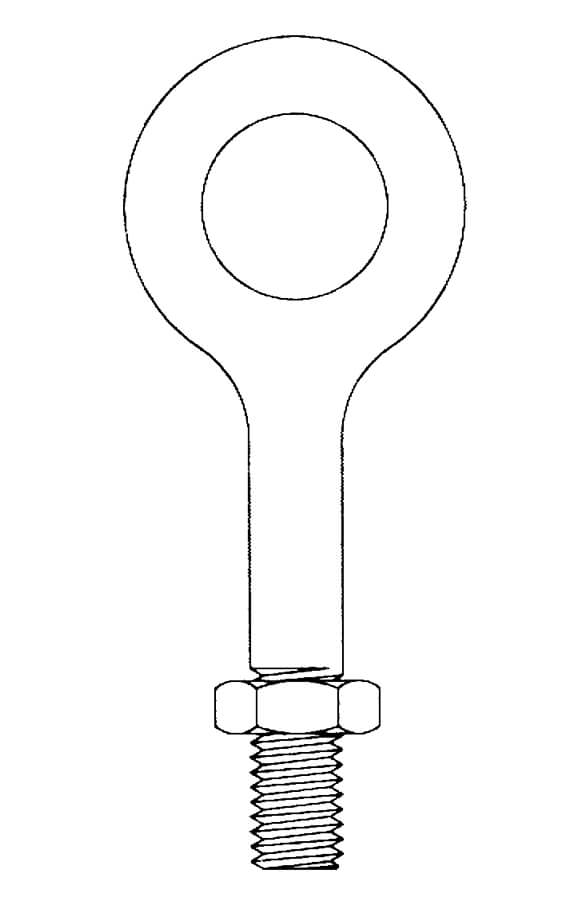
G-291
Regular Nut
Eye Bolt
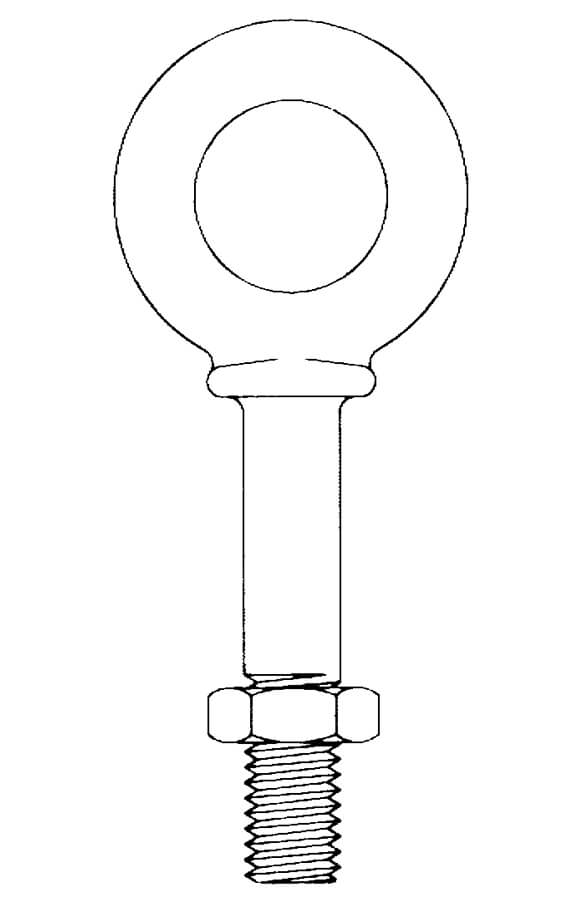
G-277
Shoulder Nut
Eye Bolt
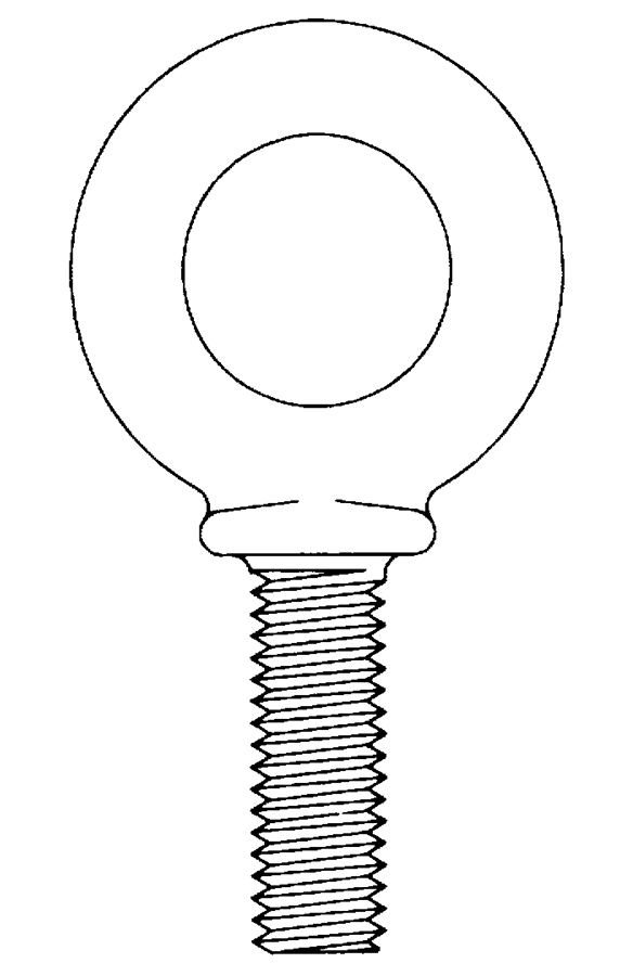
G-279
Machinery Nut
Eye Bolt
Important Safety Information —
Read & Follow
Inspection/Maintenance Safety:
- Always inspect eye bolt before use.
- Never use eye bolt that shows signs of wear or damage.
- Never use eye bolt if eye or shank is bent or elongated.
- Always be sure threads on shank and receiving holes are clean.
- Never machine, grind, or cut eye bolt
Assembly Safety:
- Never exceed load limits specified in Table 1.
- Never use regular nut eye bolts for angular lifts
- Always use shoulder nut eye bolts (or machinery eye bolts) for angular lifts.
- For angular lifts, adjust working load as follows:
| Direction of Pull | Adjusted Working Load |
| 45 degrees | 30% of rated working load |
| 90 degrees | 25% of rated working load |
- Never undercut eye bolt to seat shoulder against the load.
- Always countersink receiving hole or use washers to seat shoulder.
- Always screw eye bolt down completely for proper seating.
- Always tighten nuts securely against the load.
| Table 1 (In-Line Load) | |
| Size (in.) | Working Load Limit (lbs.) |
| 1/4 | 650 |
| 5/16 | 1200 |
| 3/8 | 1550 |
| 1/2 | 2600 |
| 5/8 | 5200 |
| 3/4 | 7200 |
| 7/8 | 10600 |
| 1 | 13300 |
| 1 1/4 | 21000 |
| 1 1/2 | 24000 |
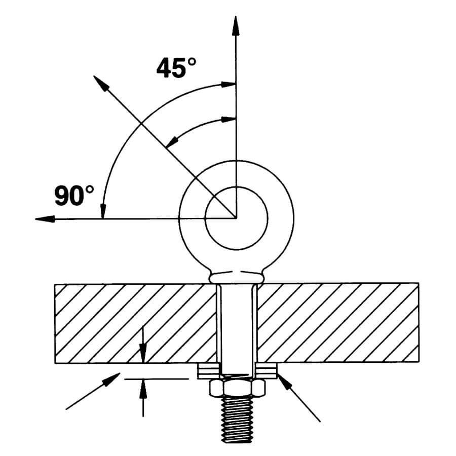
IN – LINE
Shoulder Nut Eye Bolt —
Installation for Angular Loading
- The threaded shank must protrude through the load sufficiently to allow full engagement of the nut.
- If the eye bolt protrudes so far through the load that the nut cannot be tightened securely against the load, use properly sized washer to take up the excess space BETWEEN THE NUT AND THE LOAD.
- Place washers or spacers between nut and load so that when the nut is tightened securely, the shoulder is secured flush against the load surface.
- Thickness of spacers must exceed this distance between the bottom of the load and the last thread of the eye bolt.
WARNING:
- Loads may slip or fall if proper eye bolt assembly and lifting procedures are not used.
- A falling load may cause serious injury or death.
- Read and understand both sides of these instructions, and follow all eye bolt safety information presented here.
- Read, understand and follow all information in diagrams and charts below before using eye bolt assemblies
Regular Nut & Shoulder Nut Eye Bolt — Installation for In-line Loading Warnings and Application Instructions
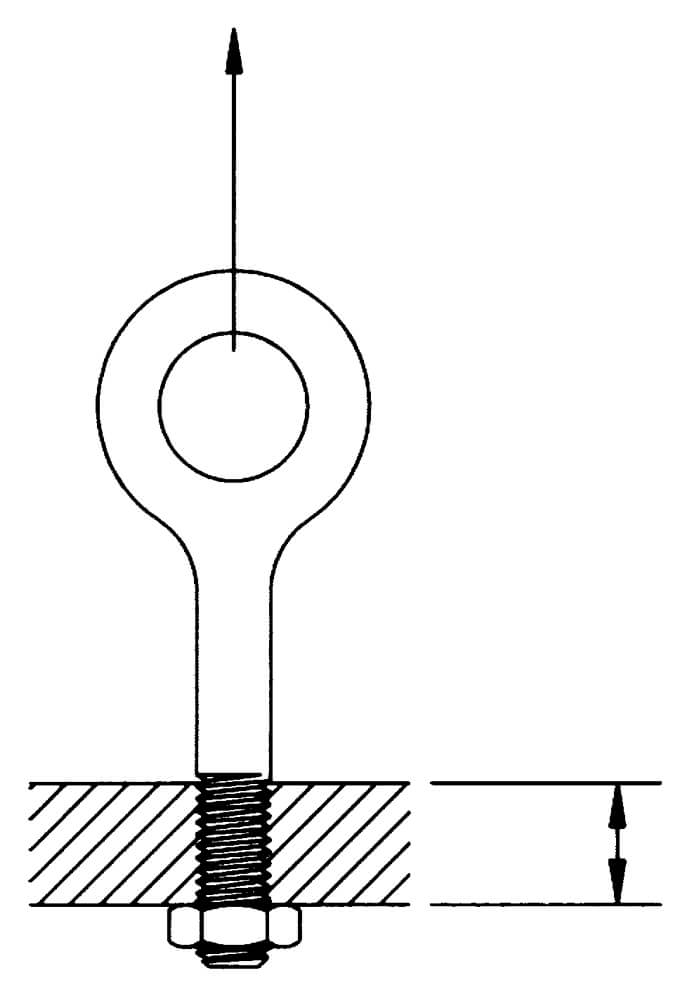
RIGHT
More than one eye bolt diameter of threads, only (1) nut required.
Tighten hex nut securely against load
Tighten hex nut securely against load
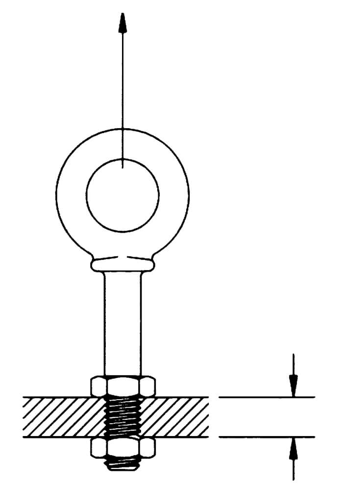
RIGHT
One eye bolt diameter of threads or less, use two (2) nuts.
Tighten hex nut securely against load
Tighten hex nut securely against load
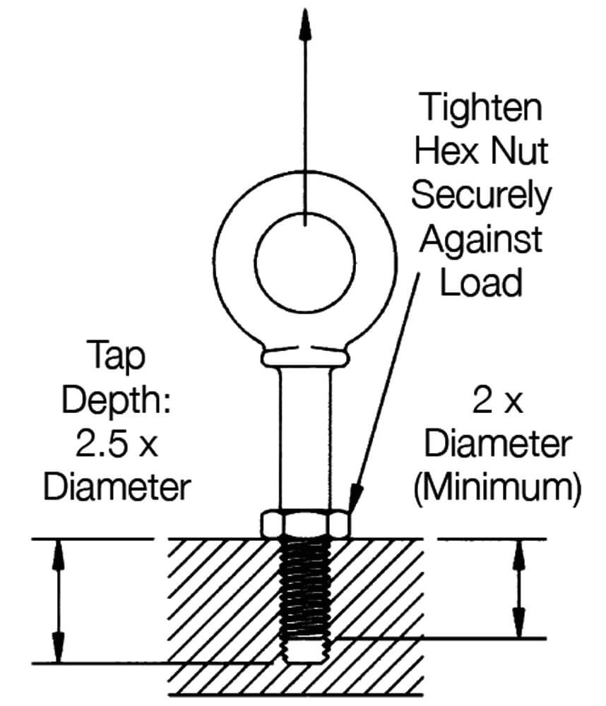
RIGHT
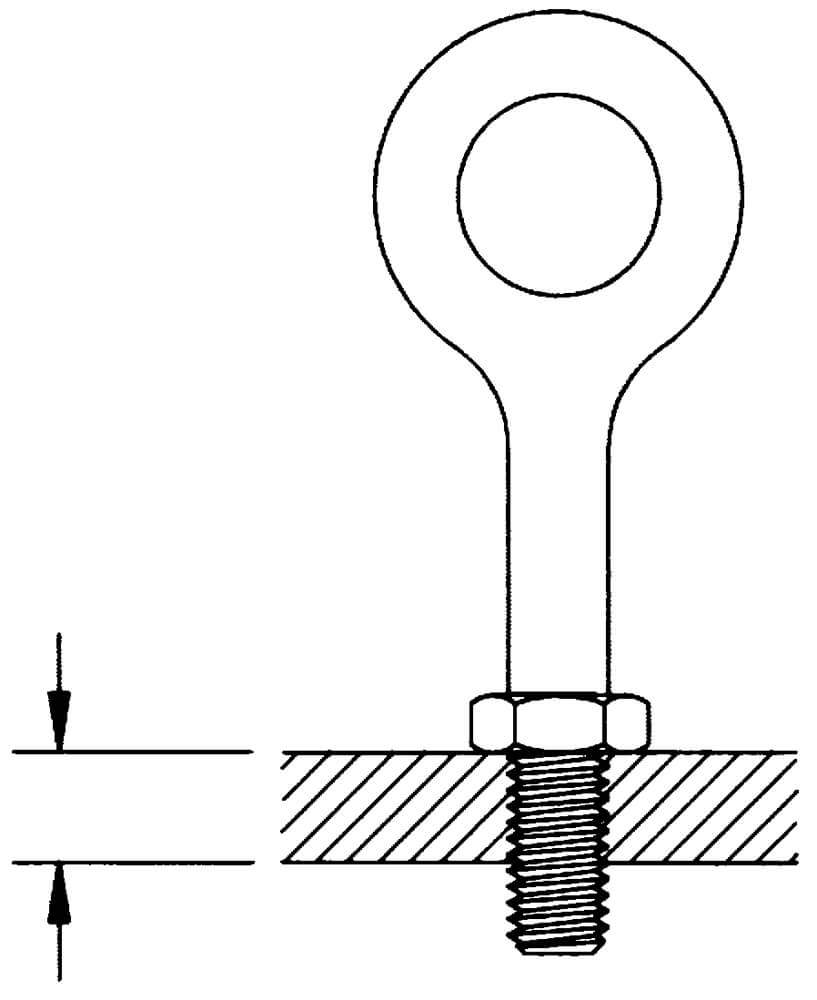
WRONG
One eye bolt diameter or less
Operating Safety
- Always stand clear of load.
- Always lift load with steady, even pull – do not jerk.
- Always apply load to eye bolt in the plane of the eye – not at an angle.
- Never exceed the capacity of the eye bolt–see Table 1.
- When using lifting slings of two or more legs, make sure the loads in the legs are calculated using the angle from the vertical to the leg and properly size the shoulder nut or machinery eye bolt for the angular load.
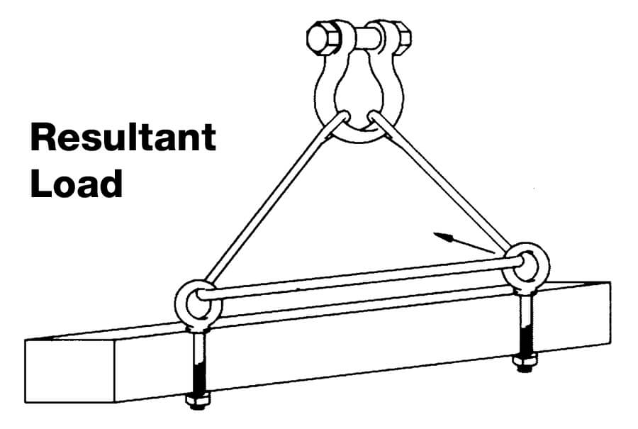
WRONG
Do not reeve slings from one eye bolt to another.
This will alter the load and angle of loading on the eye bolt.
This will alter the load and angle of loading on the eye bolt.
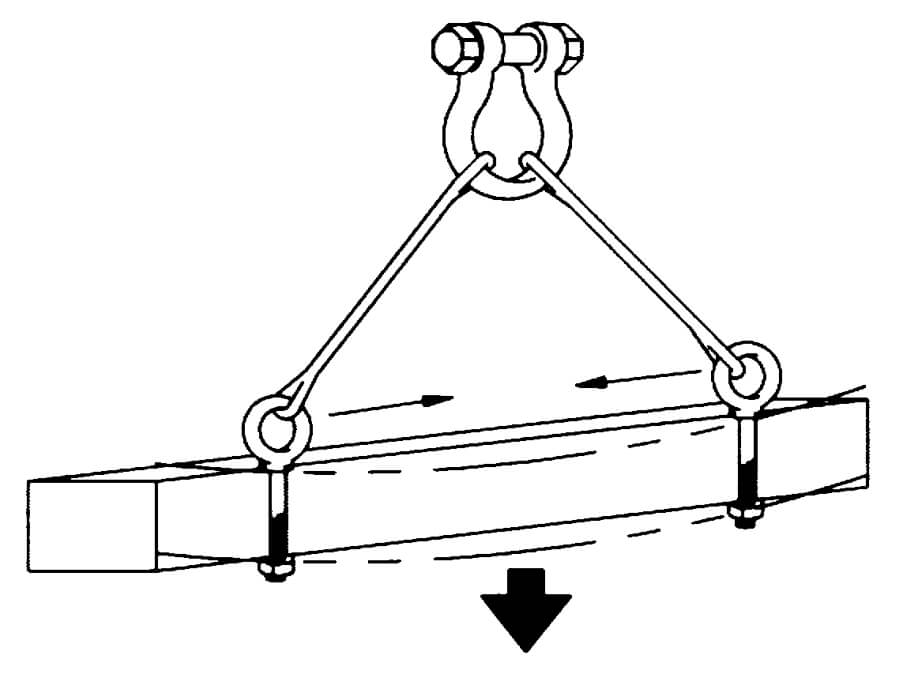
After slings have been properly attached to the eye blots, apply force slowly. Watch the load carefully and
be prepared to stop applying force if the load starts buckling.
Buckling may occur if the load is not stiff enough to resist the compressive forces which result from the angular loading.
be prepared to stop applying force if the load starts buckling.
Buckling may occur if the load is not stiff enough to resist the compressive forces which result from the angular loading.
WARNING:
- Loads may slip or fall if proper eye bolt assembly and lifting procedures are not used.
- A falling load may cause serious injury or death
- Read and understand both sides of these instructions, and follow all eye bolt safety information presented here.
- Read, understand and follow all information in diagrams and charts below before using eye bolt assemblies.
Machinery Eye Bolt — Installation for In-Line & Angular Loading
Warnings and Application InstructionsWarnings and Application Instructions
These eye bolts are primarily intended to be installed into tapped holes.
1. After the loads on the eye bolts have been calculated, select the proper size eye bolt for the job.
For angular lifts, adjust working load as follows:
These eye bolts are primarily intended to be installed into tapped holes.
1. After the loads on the eye bolts have been calculated, select the proper size eye bolt for the job.
For angular lifts, adjust working load as follows:
| Direction of Pull | Adjusted Working Load |
| 45 degrees | 30% of rated working load |
| 90 degrees | 25% of rated working load |
2. Drill and tap the load to the correct sizes to a minimum depth of one-half the eye bolt size beyond
the shank length of the machinery eye bolt.
3. Thread the eye bolt into the load until the shoulder is flush and securely tightened against the load.
4. If the plane of the machinery eye bolt is not aligned with the sling line, estimate the amount of
unthreading rotation necessary to align the plane of the eye properly.
5. Remove the machinery eye bolt from the load and add shims (washers) of proper thickness to
adjust the angle of the plane of the eye to match the sling line. Use Table 2 to estimate the required
shim thickness for the amount of unthreading rotation required.
| Table 2 | |
| Eye Bolt Size (in.) | Shim Thickness Required to Change Rotation 90° (in.) |
| 1/4 | 0.0125 |
| 5/16 | 0.0139 |
| 3/8 | 0.0156 |
| 1/2 | 0.0192 |
| 5/8 | 0.0227 |
| 3/4 | 0.0250 |
| 7/8 | 0.0278 |
| 1 | 0.0312 |
| 1 1/4 | 0.0357 |
| 1 1/2 | 0.0417 |
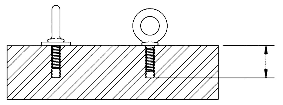
Shim added to change eye alignment 90° Minimum tap depth is basic shank length plus one-half the nominal eye bolt diameter.

